Electrification
Croatian language - Hrvatski jezik
The history of railway
electrification in Europe
A
modern observer could wonder why there are so many different electrification
systems in Europe, and whether they might be unified soon. The main reason for
such a difference is the fact that since the beginning of the twentieth century
electric equipment (traction motors, current supplying system) has been
constantly improved. As a single country was ready to introduce the
electrification (the last was Greece, and Albania has not yet), the best system
available at the time was adopted, and the required number of corresponding
traction devices was purchased.
The
first achievements of electric traction were apt for shorter lines with a minor
charge only, hence for trams. The lines were powered at 150 V DC, and the power
of the unit amounted up to 7,5 hp. After 1888, the tension reached 600 V, the
maximum power was about 40 hp, and this made viable the electrification of
suburban commuter trains and underground railways. The electric motors were at
an early stage; for instance, they lacked auxiliary poles and compensatory
spools.
The
first electric locomotive to appear on a mainline was the one between Baltimore
and Ohio. It was inaugurated in 1895, and powered at 650 V DC. However, this
current system was unsuitable for longer relations and more powerful units.
About
1900, there was still no DC motor of a greater power available, so the tri-phase
AC asynchronous motor had to be used. This 750 V system, with the lowered
frequency of 40 Hz, constituted the first true railway electrification system.
It was first utilised in Switzerland. In northern Italy, the tri-phase
electrification at 3,300 V ~ 15 Hz spread until 1928. The engines were furnished
with inductive asynchronous motors. Nevertheless, this current system proved to
be rather complicated, since two isolated overhead wires were required (the
third phase was at the rails), which was especially awkward over the switches.
Furthermore, what increased the costs was the fact that the railway network
could not be simply connected (without conversions) to the public power network.
Therefore, a simplified solution had to be invented. The subsequent researches
took two directions, involving alternating and direct current.
With
the AC power, the standard frequency of 50 Hz still could not be used, but had
to be lowered in order to avoid noxious effects at motor collectors. The
frequency was reduced to one third, namely to 16 2/3 Hz (16.7 Hz). The first
unit powered at 15,000 V ~ 16 2/3 Hz was built in 1905 in Switzerland. It had
total hourly power of 205 hp. At that stage, electrification could be spread all
over Europe. This current system was adopted in 1909 by Switzerland and Germany,
in the following year by Sweden, in 1914 by Austria, and in 1922 by Norway. By
1928, about 10,000 km of rail tracks worldwide was electrified at 15,000 V ~ 16
2/3 Hz.
On
the other side, the essential problem with DC system was the construction of
serial motor for a greater tension and power. Auxiliary poles were initially
used in 1903, and mercury rectifiers were constantly developed. Among the first
important lines powered at 3,000 V DC was the Chicago—Milwaukee—St. Paul
mainline in 1915. This system was adopted by Spain in 1922, by Italy in 1928, by
USSR, Belgium and Poland in 1926, and after the World War II by former
Czechoslovakia and Yugoslavia. On the other hand, France decided in 1920 to
adopt the 1,500 V DC system, and there were approximately 5,000 km electrified
by 1948. This voltage was subsequently accepted by Holland and England.
The
mono-phase current system with normal frequency of 50 Hz was first performed in
Hungary in 1931 (Budapest—Hegyeshalom) with the tension of 15,000 V. However,
the locomotive was too complicated because it contained tension and phase
converter for asynchronous traction motor. In France, tests were performed from
1950 till 1952 with 50 Hz AC. The final decision was 25,000 V ~ 50 Hz, and this
electrification was first applied in France in 1955, and subsequently in
Hungary, USSR, England, Portugal, ex-Yugoslavia, Bulgaria, Rumania and Turkey.
The locomotives of this system have a variety of traction motors. The best
solution proved to be locomotive with transformer, rectifier and DC traction
motor(s).
During
the development of electric traction, many electric systems emerged, but only
four of them endured and made standards: 1,500 V DC; 3,000 V DC; 15,000 V ~ 16
2/3 Hz; 25,000 V ~ 50 Hz. The most successful and suitable is the last one (with
normal frequency), which is being introduced on all newly electrified lines,
unless the compatibility with the previously electrified lines is to be
retained. Its arguments are: the highest tension of the network (i.e. minimum
voltage decrements), the lightest wiring, the fewest number of electric stations
required, the possibility of direct connection to any public power network, easy
adjustment of traction motors voltage using transformer and rectifier, which
enables the utilisation of serial DC motors. The other powering systems involve
about 10 to 15 % higher costs.
Today,
the problems with international trains passing through different electrification
zones are successfully eluded by construction of multiple powered engines and
electric motor units. This is possible at relatively low costs; only the
installation of appropriate transformers is required, the other components,
including the traction motors, remain the same. Sometimes, the multiple units
have to be equipped with different pantographs due to technical distinctions of
the catenaries.
Technical features of the four
major electrification systems
The
electric stations of DC systems have to be relatively close to each other,
because of the low tension; the average distance amounts from 15 to 30 km. A
higher cross section of the wires is needed, 300 to 500 mm2, for
which reason double contact wiring is used. This network is always powered by
two electric stations simultaneously: the locomotive receives more power from
the nearer station. If a line has two tracks, their wiring can be connected to
avoid greater tension decrement.
The
electric stations of AC 25,000 V ~ 50 Hz system can be placed 40 to 60 km apart.
The average cross section of the wiring amounts 150 mm2. The powering
of the catenary is not bi-directional, but one-sided: each electric station
powers the locomotive only half the way to the next station; there is an
isolated neutral conductor in the middle, separating the two power areas. The
neutral conductor is used to avoid spanning the zones of two powering stations,
which might be connected to different phases of the public electric network.
Beginning of such an isolated zone is marked by a red »L« sign, and a rotated
black »L« sign is placed at the end. Sometimes is switching off the locomotive
demanded, and only one pantograph can be risen, to prevent connecting the
separated zones over the pantographs. There are also separators, which
facilitate connecting the wiring to another electric station, if one is out of
use. The wiring of a double track can be connected as well, but only within the
same powering areas.
There
are three major types of electric catenary: light catenary consists of one
supporting wire and one contact wire (the mono-phase systems of 16 2/3 Hz and 50
Hz); normal catenary includes one supporting wire and two contact wires (3,000 V
DC system), while the complex catenary includes one supporting wire and an
auxiliary wire supporting two contact wires (1,500 V DC system).
There
are also three ways of compensating thermal dilatation of the catenary. The
catenary can be uncompensated, semi-compensated and (fully) compensated.
Uncompensated catenary is found on short tracks at stations, operated at low
speed. With the semi-compensated catenary, the supporting wire is fixed, and the
contact wire tensed with weights. The compensated catenary has both the
supporting and conductor wire tensed together. It is suitable for high-speed
traffic (exceeding 200 km/h). The contact wire is led in zigzag manner, 20 to 25
cm leftwards or rightwards away from the central line of the track, to reduce
wearing out of the pantographs.
Electrification in Croatia
The first electrified line in Croatia was Rijeka—Pivka (Slovenia). Total length of the line was 64 km, of which 28 km (Rijeka—Šapjane) pertain to Croatia. From 1952 to 1966, the electrification of Zagreb—Rijeka mainline (229 km) was carried out with 3,000 V DC system. By mid 1960-s, former Yugoslav Railways decided to utilise 25,000 V ~ 50 Hz current system.
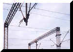
25 000 V 50 Hz console
The first track assigned for
the new electrification was Zagreb—Belgrade mainline, the most important line
of ex-Yugoslavia. The electrification was finished by the beginning of 1969.
By
the middle of the year, the Sarajevo (Bosnia)—Ploče line was completed (with
22 km in Croatia), fully electrified with the new powering system. The
electrification of Zagreb—Koprivnica line was carried out by 3rd of October
1981.
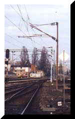
3000 V= console
Re-electrification of Zagreb—Rijeka
mainline
After
the complete electrification of the line, the fourth and fifth platform of
Zagreb Main Railway Station were powered at 3,000 V DC, while the remainder of
the station had the 25,000 V ~ 50 Hz electrification. The bridge over the Sava
in Zagreb had also two separated tracks: the easternmost heading towards Sisak
and Bosnia was AC powered, and the other, directed towards Rijeka, was powered
at 3,000 V DC. In mid 1980-s, an initiative was risen for re-electrification of
Zagreb—Rijeka mainline. This was carried out from Zagreb to Moravice (139 out
of 229 km). The remaining 90 km to Rijeka are still DC powered, which demands
the locomotive change in Moravice.
In
1999, the 24 km long track section between Drivenik and Škrljevo on Zagreb—Rijeka
mainline underwent general reparation. Subsequently, the catenary had to be
adjusted to the newly repaired tracks. The required adjustments could not be
carried out using the existing 3,000 V consoles, because of major changes
affecting rail level and central axle of the track. This made a good opportunity
for replacing all the old, worn-out 3,000 V consoles with new 25,000 V
mono-phase consoles and corresponding catenary equipment. The old catenary was
only semi-compensated, while the new one is fully-compensated. The catenary
replacement took place from 3rd March until 19th May 2000. It should be pointed
out that all the substitution material had been produced in Croatia. One
experimental catenary block was replaced earlier, between Moravice and Brod
Moravice stations. Currently, the whole section Moravice—Rijeka is powered at
3,000 V DC until the complete catenary replacement is done. The result seems
very odd: 25,000 V consoles are equipped with 3,000 V DC double wiring, because
this voltage requires a greater cross section of the conductor.
![]()
![]()