|
|
|
TGVweb > World Speed Record > Trainset Preparations |
Serve this page from: California, USA / Pisa, Italy |
You can skip directly to the pictures
In the early stages when operation TGV 117 was still being defined, several criteria were settled upon to focus the preparation of a test train. These were aerodynamics, traction and electrical systems, rail and catenary contact, braking, and last but not least, comfort.
The basic purpose of the test program was to push the envelope of the TGV system, and to characterize its behavior at very high speeds. With this in mind, it only made sense to start with a stock TGV trainset and to modify it as little as possible. Brand new TGV Atlantique trainset number 325 (25th of 105 in the Atlantique series) was arbitrarily chosen to be the starting point of the modifications. It should be emphasized that there was nothing special about this trainset, and that it was returned to its intended state after the test program to enter revenue service. Today, the only distinguishing feature on 325, as compared to other Atlantique trainsets, is a blue ribbon painted across the nose, and bronze plaques bolted to the sides of the two power cars to commemorate the event.
Trainset 325, First Version
In preparation for the first round of testing, modifications began by shortening the train from its usual 10 trailers to only 4 trailers, resulting in a significant increase in power to weight ratio. The resulting consist was: power car TGV24049, Trailer R1 TGVR241325, Trailer R4 TGVR244325, Trailer R6 TGVR246325, Trailer R10 TGVR240325 and power car TGV24050. Train length was down to 125 m (381 ft.) from 237 m (777 ft.) and weight was down to 300 metric tons from 490 metric tons.
The aerodynamics of a TGV Atlantique are already quite good, and improvements were few. It was decided that 325 would have a "front" and "rear" for the high speed runs, to simplify the modifications. Usually a TGV trainset is symmetric and reversible, but 325's two power cars, 24049 and 24050, were defined as leading and trailing units, respectively. On the roof of lead unit 24049, the pantographs were removed and the roof fairing extended over the opening; the same was done to the 1500 V DC pantograph on trailing unit 24050. Only one pantograph was to be used at high speed: the stock Faiveley GPU unit remaining on unit 24050. As in normal TGV running, the lead unit was to be fed power from the trailing unit through the roof line running the length of the train. Further improvements, such as rubber membranes covering the gaps between the trailers, and a rear spoiler on unit 24050 were considered, but abandoned.
The synchronous AC traction motors on 24049 and 24050 could not be allowed to rotate too fast, because of limitations in the switching frequency of the supply electronics. Technicians had decided upon 4000 rpm at 420 km/h (261 mph) to be the optimal ratio, after testing trainset 325 at high speeds with stock traction equipment. The new traction ratio was achieved by changing the transmission gearing and increasing the wheel diameter. Just as with the 1981 test campaign on TGV PSE number 16, 1050 mm (41 in.) wheels replaced the stock 920 mm (36 in.) wheels under 24049 and 24050.
To prevent electrical problems, semiconductor components (especially thyristors) were selected with special regard to quality. The main transformers in both power cars were replaced by larger models, each able to handle 6400 kW (8500 hp), or double the usual load, on a fairly continuous basis. Extensive tests were conducted on the electrical systems, to establish how far they could be pushed. The resulting ratings insured that acceptable heat levels would never be exceeded in testing.
Next, the wheel-rail interface was attended to. Axle bearings were unmodified items, broken in for 10,000 km in revenue service on the TGV Sud-Est. Yaw dampers were stiffened, and doubled up on each side for a total of four yaw dampers on each truck, for redundancy in case of a high speed failure. As a result of earlier testing and computer simulations, transverse dampers were stiffened on the power trucks.
The 1981 test campaign provided valuable data and computer models for interaction of the pantograph with the catenary contact wire, and shed light on the very sensitive dynamics. Very large vertical wire excursion (over 30 cm, or 1 foot) had been observed in the 1981 tests, and were blamed on the pantograph catching up with the travelling wave it set up in the contact wire. For this reason, it was not only necessary to modify the catenary to increase the travelling wave speed, but also to fine-tune the pantograph itself.
The pantograph used on 325 was the stock Faiveley GPU. The wiper assembly on this pantograph weighs under 8 kg (18 lb.) and is mounted on a vertical shock absorber with 150 mm (6 in.) travel. The main structure of the pantograph is constructed of cylindrical tubing, which (Faiveley claims) reduces the pantograph's sensitivity to random variations in environmental factors. The only modifications to the GPU pantograph were an increase in the stiffness of the pneumatic dampers, and a reduced total aerodynamic lift of the structure.
The suspension on the trailers was jacked up by 20 mm (1 in) by overinflating the secondary suspension air bladders and inserting shims, to provide additional suspension travel and to make up for the larger wheels on the power cars.
The brakes on the trailers were tuned to allow a heat dissipation of 24 MJ per disk instead of the usual 18 MJ, with a total of 20 discs.
Many of the modifications listed above, including the synchronous traction motors, were tested at speeds over 400 km/h on trainset 88 of the TGV Sud-Est. In one high speed test, technicians attempted to provoke a truck into unstable oscillation by drastically reducing the yaw damping, but failed to achieve this.
Finally, most of the seating in trailer R1 was removed and the space was transformed into a labratory, to process and record test data on vehicle dynamics, overhead contact and dynamics, tractive effort, aerodynamics, interior comfort and noise, and a host of other parameters.
On 30 November 1989, trainset 325 emerged from the Châtillon shops and set out for the test tracks for its first test run. Technicians at Châtillon put 4500 hours of work into the modifications, which was impressive when one considers that their first priority was the routine maintenance of the TGV Atlantique trainsets in revenue service. The first campaign of testing with 325, until 1 February 1990, is summed up in the chronology of the record runs.
Trainset 325, Second Version
On 1 February 1990 at 15:30, 325 returned to the Châtillon shops for the long term. At this time, 325 had set a world record at 482.4 km/h (299.8 mph). Technicians had a 1 March deadline to perform further modifications designed to make possible further data collection and a 500 km/h (311 mph) publicity stunt. This second round of modifications was intended to take direct advantage of the experience gained in the first round.
The axles on 24049 and 24050 were removed and on 2 February, shipped to the Bischheim shops in eastern France for fitting with even larger 1090 mm (43 in) wheels. The lead axle on 24049 was fitted with strain gauges, and returned to Châtillon 8 days after the other axles on 22 February. Initially, the second axle on 24049 had also been scheduled to be fitted with strain gauges, but the 1 March deadline did not allow enough time. To accomodate the bigger wheels, special brake pads had to be manufactured for the brake shoes on 24049 and 24050. With 15 mm (5/8 in) of thickness, only two emergency stops were guaranteed.
On 6 February, the trailers were jacked up and trailer R6 was removed. This brought 325 to the minimum possible consist, since the bar trailer R4 fuctions as the "keystone" of the articulated design of the TGV. 325 now weighed in at 250 metric tons and measured 106 m (348 ft) nose to tail. From 7 to 14 February, the three remaining trailers underwent further modifications. The 25 kV roof supply line to feed the lead unit was replaced by a single cable; this allowed the removal of the insulators supporting the line over the space between trailers, which protruded in the airstream. Rubber membranes were installed to cover the gaps between the trailers, and the Y237B trucks were jacked by 40 mm (1.5 in).
In the gap between power cars and trailers, large airdams were installed. These "snow shields", mounted beneath the couplers, were designed to prevent the formation of a low pressure area between the vehicles, which had induced significant drag in the earlier testing. On the power cars, sheet metal shields were added over the trucks, and the front airdam was extended downwards by 10 cm (4 in) to compensate for the larger wheels. Finally, a removable spoiler was installed on the nose of trailing unit 24050.
The aerodynamic improvements were supposed to yield a 10% reduction in drag. In the previous round of testing, the atmospheric drag force had reached 9 metric tons (force) at a speed of 460 km/h (286 mph). On the new version of 325, this magnitude of drag was not expected before 500 km/h (311 mph).
On 27 February 1990, after the trainset was coupled together, 325 rolled out from the Châtillon shops for the second time, 2 days ahead of schedule. This time, 2000 hours of shop labor were required to accomplish the changes. The second campaign of testing, culminating in the standing world speed record of 515.3 km/h (320.3 mph) is summed up in the chronology of the record runs.
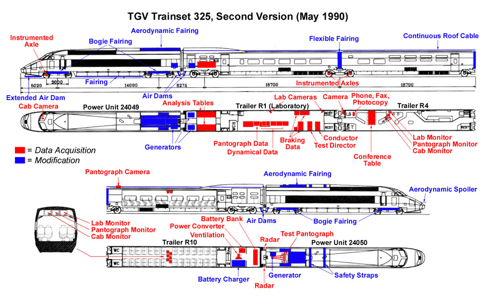
Trainset Configuration on 18 May 1990
Click on the image to make it bigger
Pictures from La Vie du Rail
Click on the pictures to make them bigger
2 
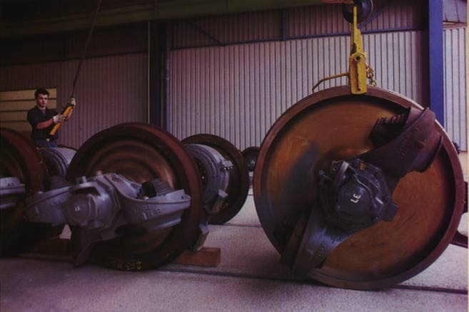
Picture 1: Larger wheels arriving at Châtillon.
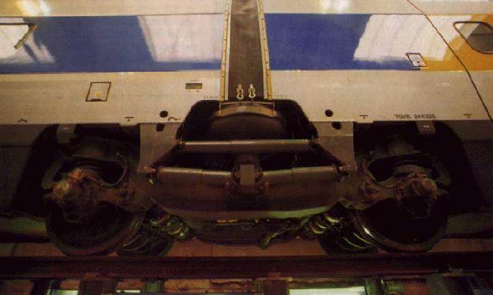
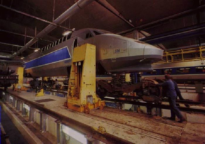
Picture 2: The end of a trailer. The four brake discs per axle are clearly visible here, as are the large pneumatic suspension bladders. At left is a power car with its nose open.
4 
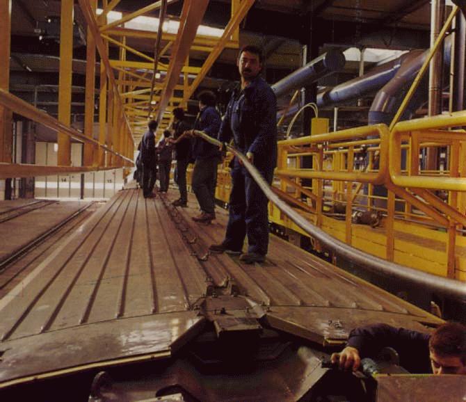
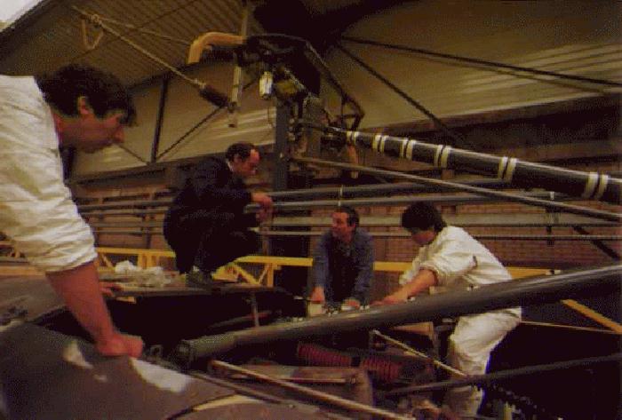
Picture 3: Shop workers at Châtillon installing the new 25 kV roof cable.
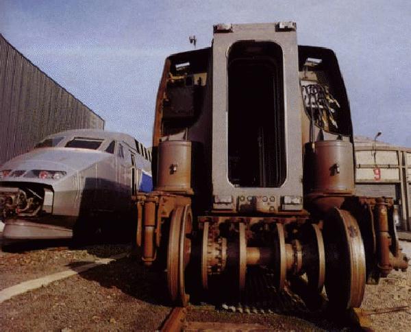
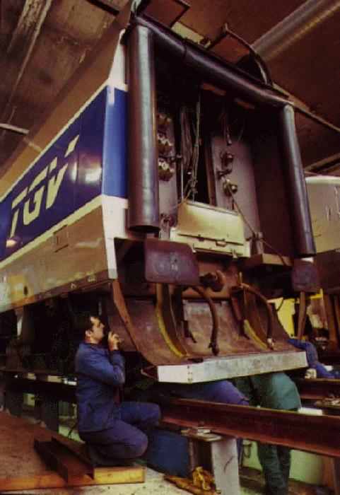
Picture 4: Installation of the air dam at the rear of a power car. Notice the standard buffer and screw link couplers.
6 
Picture 5: The telemetry axle on 24049, being fitted with strain gauges.
Picture 6: The pantograph being inspected in the shop.
8 
Picture 7: Side view of a trailer truck. Note the double yaw dampers, beneath the trailer-to-trailer damper, and rubber membrane over the gap between trailers.
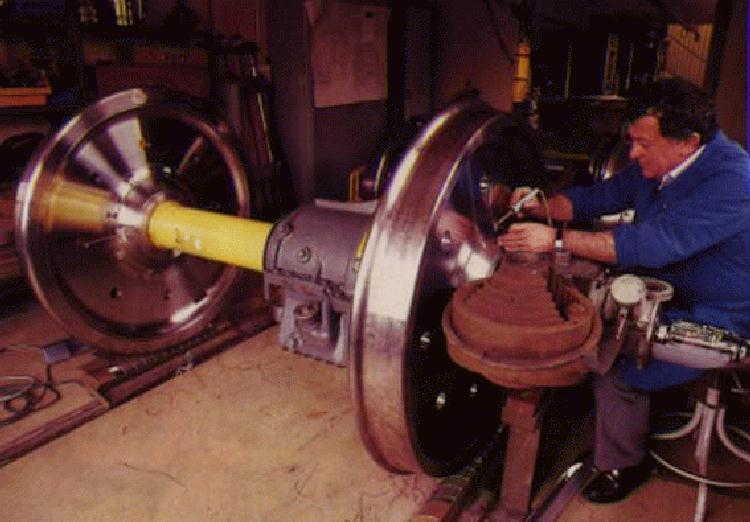
Picture 8: After having their large wheels installed, the power trucks are rolled back under 24049.
10 
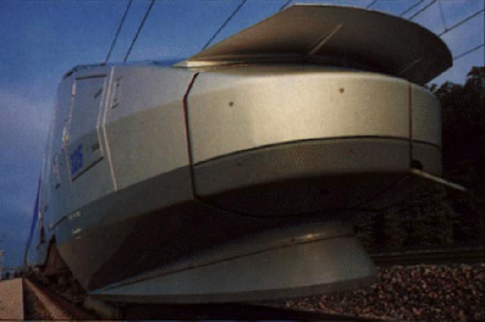
Picture 9: The rear spoiler on 24050.
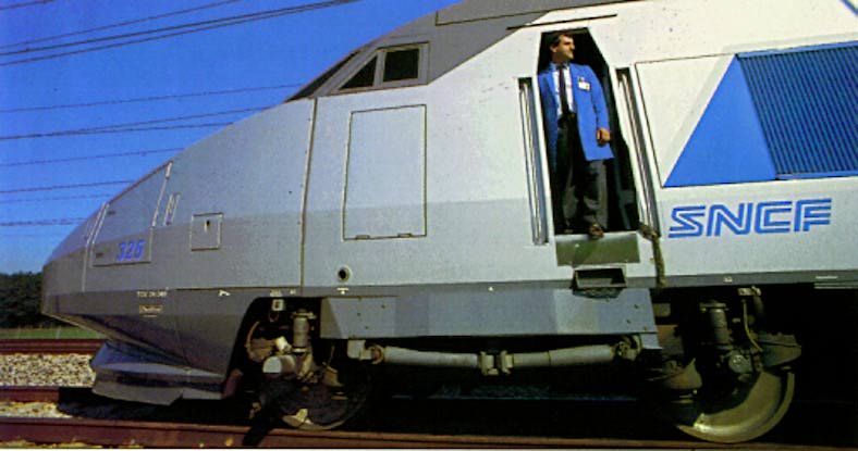
Picture 10: The nose of 24049. Engineer Michel Massinon stands in the door. Note the shields over the truck, the doubled yaw dampers, and the skirt under the front airdam.Photo Credits: All photos by C. Recoura/LVDR
TGVweb > World Speed Record > Trainset Preparations