href = "jpg/construction4.jpg">
The rails are placed on the ties.
Note how flexible they are. Photo: C. Recoura / LVDR
The sections of rail are welded together using thermite. Conventional
welding (using some type of flame) does not work well on large metal
pieces such as rail, since the heat is conducted away too quickly.
Thermite is better suited to this job. It is a mix of aluminum powder
and rust (iron oxide) powder, which reacts to produce iron, aluminum
oxide, and a very large amount of heat. This last property is what
makes it ideal to join pieces of rail. Before the rail is joined, its
length must be adjusted very accurately. This ensures that the
thermal stresses in the rail after it is joined into one continuous
piece do not exceed certain limits, resulting in lateral kinks (in hot
weather) or breaks (in cold weather). The joining operation is
performed by an aluminothermic welding machine which is equipped with
a rail saw, a weld shear and a grinder. When the thermite welding
process is complete, the weld is ground down to the profile of the
rail, resulting in a seamless connection between adjoining sections.
Thermal stresses in the rail due to varying ambient temperatures are
absorbed without longitudinal strain, except near bridges where an
expansion joint is sometimes used.
|
 The next
step consists of stuffing a deep bed of ballast underneath the new track.
The ballast arrives in a train of hopper cars pulled by one or two
diesels. Handling this train is challenging, since the ballast must be
spread as evenly as possible. If the train stops, ballast can pile over
the rails and derail it. A first layer of ballast is dumped directly onto
the track, and a tamping-lining-levelling machine, riding on the rails,
forces the stones underneath the ties. Each pass of this machine can
raise the level of the track by 8 cm (3 inches), so several passes of
ballasting and of the machine are needed to build up a layer of ballast at
least 32 cm (1 foot) think under the ties. The ballast is also piled
thick on each side of the track for lateral stability. The machine
performs the initial alignment of the track. Next, a ballast regulator
distributes the ballast evenly. Finally, a dynamic vibrator machine
shakes the track to perform the final tamping, effectively simulating the
passing of 2500 axles. The next
step consists of stuffing a deep bed of ballast underneath the new track.
The ballast arrives in a train of hopper cars pulled by one or two
diesels. Handling this train is challenging, since the ballast must be
spread as evenly as possible. If the train stops, ballast can pile over
the rails and derail it. A first layer of ballast is dumped directly onto
the track, and a tamping-lining-levelling machine, riding on the rails,
forces the stones underneath the ties. Each pass of this machine can
raise the level of the track by 8 cm (3 inches), so several passes of
ballasting and of the machine are needed to build up a layer of ballast at
least 32 cm (1 foot) think under the ties. The ballast is also piled
thick on each side of the track for lateral stability. The machine
performs the initial alignment of the track. Next, a ballast regulator
distributes the ballast evenly. Finally, a dynamic vibrator machine
shakes the track to perform the final tamping, effectively simulating the
passing of 2500 axles.
|
The tamping machine.
Photo: C. Recoura / LVDR
The ballast regulator. Photo: C. Recoura / LVDR
|
 Now that
the first track is almost complete, work begins on the adjacent track.
This time, however, it is not necessary to lay a temporary track. Trains
running on the first track bring the ties, and then the rail, which is
unloaded directly onto the ties by dispensing arms that swing out to the
proper alignment. The Nabla fasteners are secured, and the ballast is
stuffed under the track as before. Now that
the first track is almost complete, work begins on the adjacent track.
This time, however, it is not necessary to lay a temporary track. Trains
running on the first track bring the ties, and then the rail, which is
unloaded directly onto the ties by dispensing arms that swing out to the
proper alignment. The Nabla fasteners are secured, and the ballast is
stuffed under the track as before.
|
Left: a ballast train
arrives behind two 67000-class diesels. Middle: work on the second
track. Right: the tamper and regulator at work on the first track.
Photo: C Recoura / LVDR
|
 The two
tracks are now essentially complete, but the work on the line is not
finished. The catenary masts need to be erected, and the wire strung on
them. Catenary installation is not complicated; it will suffice to give a
brief summary of specifications. The steel masts are I-beams, placed in a
concrete foundation up to 63 m (206 ft) apart. The supports are mounted
on glass insulators. The carrier wire is bronze, 65 mm^2 cross section,
14 kN (3100 lb) tension. The stitch wire is bronze, 15 m (49 ft) long, 35
mm^2 cross section, The droppers are 5 mm stranded copper cable. The
contact wire is hard drawn copper, 120 mm^2, flat section on the contact
side, 14 kN tension. The maximum depth of the catenary (distance between
carrier and contact wires) is 1.4 m (4 feet). The contact wire can rise a
maximum of 240 mm (9 inches) but the normal vertical displacement does not
exceed 120 mm (4 inches). The two
tracks are now essentially complete, but the work on the line is not
finished. The catenary masts need to be erected, and the wire strung on
them. Catenary installation is not complicated; it will suffice to give a
brief summary of specifications. The steel masts are I-beams, placed in a
concrete foundation up to 63 m (206 ft) apart. The supports are mounted
on glass insulators. The carrier wire is bronze, 65 mm^2 cross section,
14 kN (3100 lb) tension. The stitch wire is bronze, 15 m (49 ft) long, 35
mm^2 cross section, The droppers are 5 mm stranded copper cable. The
contact wire is hard drawn copper, 120 mm^2, flat section on the contact
side, 14 kN tension. The maximum depth of the catenary (distance between
carrier and contact wires) is 1.4 m (4 feet). The contact wire can rise a
maximum of 240 mm (9 inches) but the normal vertical displacement does not
exceed 120 mm (4 inches).
Now that the catenary is complete, the track is given final alignment
adjustments down to millimeter tolerances. The ballast is then blown to
remove smaller gravel fragments and dust, which might be kicked up by
trains. This step is especially important on high speed tracks, since the
blast of a passing train is strong. Finally, TGV trains are tested on the
line at gradually increasing speeds. The track is qualified at speeds
slightly higher than will be used in everyday operations (typically 350
km/h, or 212 mph), before being opened to commercial service.
See more pictures of track construction
here in TGVweb or on the
LGV Méditeranée
official web site.
Last Update: February 2000
|
|
|
|
|
|
|
 Next, a
layer of compact gravel is spread on the trackbed. This, after being
compacted by rollers, provides an adequate surface for vehicles with
tires. TGV track laying then proceeds. The track laying process is not
particularly specialized to high speed lines; the same general technique
is applicable to any track that uses continuous welded rail. The steps
outlined below are used around the world in modern track laying. TGV
track, however, answers to stringent requirements that dictate materials,
dimensions and tolerances.
Next, a
layer of compact gravel is spread on the trackbed. This, after being
compacted by rollers, provides an adequate surface for vehicles with
tires. TGV track laying then proceeds. The track laying process is not
particularly specialized to high speed lines; the same general technique
is applicable to any track that uses continuous welded rail. The steps
outlined below are used around the world in modern track laying. TGV
track, however, answers to stringent requirements that dictate materials,
dimensions and tolerances. To begin
laying track, a gantry crane that rides on rubber tires is used to lay
down panels of prefabricated track. These are laid roughly in the
location where one of the tracks will be built (all LGVs are double
tracked). Each panel is 18 meters (60 ft.) long, and rests on wooden
cross ties. No ballast is used at this stage, since the panel track is
temporary.
To begin
laying track, a gantry crane that rides on rubber tires is used to lay
down panels of prefabricated track. These are laid roughly in the
location where one of the tracks will be built (all LGVs are double
tracked). Each panel is 18 meters (60 ft.) long, and rests on wooden
cross ties. No ballast is used at this stage, since the panel track is
temporary.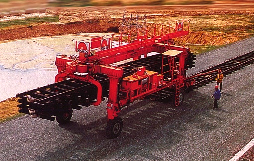
 Once the
panel track is laid, a work train (pulled by diesel locomotives) can bring
in the sections of continuous welded rail that will be used for this first
track (of two). The rail comes from the factory in lengths varying from
200 m (660 ft) to 400 m (1310 ft). Such long pieces of rail are just laid
across several flat cars; they are very flexible, so this does not pose a
problem. A special crane unloads the rail sections, and places them on
each side of the temporary track, approximately 3.5 meters (12 feet)
apart. This operation is usually carried out at night, for thermal
reasons. The rail itself is standard UIC section, 60 kg/m (40 lb/ft),
with a tensile strength of 800 Newtons per square millimeter (116,000
psi).
Once the
panel track is laid, a work train (pulled by diesel locomotives) can bring
in the sections of continuous welded rail that will be used for this first
track (of two). The rail comes from the factory in lengths varying from
200 m (660 ft) to 400 m (1310 ft). Such long pieces of rail are just laid
across several flat cars; they are very flexible, so this does not pose a
problem. A special crane unloads the rail sections, and places them on
each side of the temporary track, approximately 3.5 meters (12 feet)
apart. This operation is usually carried out at night, for thermal
reasons. The rail itself is standard UIC section, 60 kg/m (40 lb/ft),
with a tensile strength of 800 Newtons per square millimeter (116,000
psi). For the
next step, a gantry crane is used again. This time, however, the crane
rides on the two rails that were just laid alongside the temporary track.
A train of flat cars, half loaded with TGV cross ties, arrives at the site.
It is pushed by a special diesel locomotive, which is low enough to fit
underneath the gantry cranes. The cranes remove the panels of temporary
track, and stack them onto the empty half of the tie train. Next, they
pick up sets of 30 TGV ties, pre-arranged with the proper spacing (60 cm,
or 24"), using a special fixture. The ties are laid on the gravel bed
where the panel track used to be. The tie train leaves the worksite
loaded with sections of panel track.
For the
next step, a gantry crane is used again. This time, however, the crane
rides on the two rails that were just laid alongside the temporary track.
A train of flat cars, half loaded with TGV cross ties, arrives at the site.
It is pushed by a special diesel locomotive, which is low enough to fit
underneath the gantry cranes. The cranes remove the panels of temporary
track, and stack them onto the empty half of the tie train. Next, they
pick up sets of 30 TGV ties, pre-arranged with the proper spacing (60 cm,
or 24"), using a special fixture. The ties are laid on the gravel bed
where the panel track used to be. The tie train leaves the worksite
loaded with sections of panel track.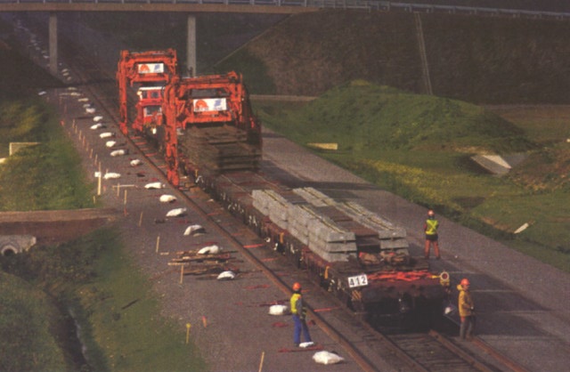
 The cross
ties are U41 twin block reinforced concrete, 2.4 m (7' 10") wide, and
weigh 245 kg (540 lb) each. They are equipped with hardware for Nabla
RNTC spring fasteners, and a 9 mm (3/8") rubber pad. (Rubber pads are
always used under the rail on concrete ties, to avoid cracking). Next, a
rail threader is used to lift the rails onto their final position on the
ties. This machine rides on the rails just like the gantry cranes, but
can also support itself directly on a tie. By doing this, it can lift the
rails, and shift them inwards over the ends of the ties, to the proper
gauge. It then lowers them onto the rubber tie cushions, and workers use
a pneumatically operated machine to bolt down the Nabla clips with a
predetermined torque. The rails are canted inward at a slope of 1 in 20;
this is clearly visible on photographs of the tie cushions.
The cross
ties are U41 twin block reinforced concrete, 2.4 m (7' 10") wide, and
weigh 245 kg (540 lb) each. They are equipped with hardware for Nabla
RNTC spring fasteners, and a 9 mm (3/8") rubber pad. (Rubber pads are
always used under the rail on concrete ties, to avoid cracking). Next, a
rail threader is used to lift the rails onto their final position on the
ties. This machine rides on the rails just like the gantry cranes, but
can also support itself directly on a tie. By doing this, it can lift the
rails, and shift them inwards over the ends of the ties, to the proper
gauge. It then lowers them onto the rubber tie cushions, and workers use
a pneumatically operated machine to bolt down the Nabla clips with a
predetermined torque. The rails are canted inward at a slope of 1 in 20;
this is clearly visible on photographs of the tie cushions.